(C) 2021 Vernon R Stanley, MD, PhD, Author | Courtney Stanley, PA-C Co-editor | ECGcourse.com, LLC | All rights reserved.
Question: True or False? The computer interpretation of the 12-lead ECG is very reliable and should be used regularly in clinical practice. (See bottom of post for answer.)
The electrical axis refers to the frontal plane. It is a vector (an arrow with direction and magnitude) pointing in the direction of the resultant depolarization wavefront (net summation) of the ventricles. Since the Left Ventricle supplies the dominate wavefront voltage and we know that this wavefront is usually in a leftward-downward direction, we would expect the electrical axis to be in this same direction. This is indeed the case as is demonstrated in Diagram #52 below. It is certainly true that the axis can be found by many different approaches; but the most straightforward approach arises from the field of mathematics, and it is the approach that I recommend.
This approach relies on the following law of mathematics: If two vectors are perpendicular to each other, the resultant vector is found by drawing the diagonal of the rectangle formed by these two vectors (demonstrated in Diagram #52 below).
Diagram #52: Normal Axis
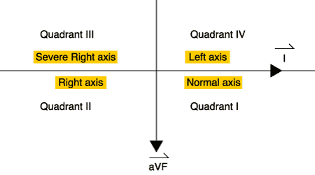
The salient points to be gleaned from this diagram are as follows:
- A NORMAL axis will have a dominantly positive Lead I and Lead avF
and the converse…
- If Lead I and Lead avF are dominantly positive…..the axis is NORMAL
* If available to the student, please see pages 68-69 of the 12-lead ECG Textbook for the other three quadrants of axes and for further discussion of axis.
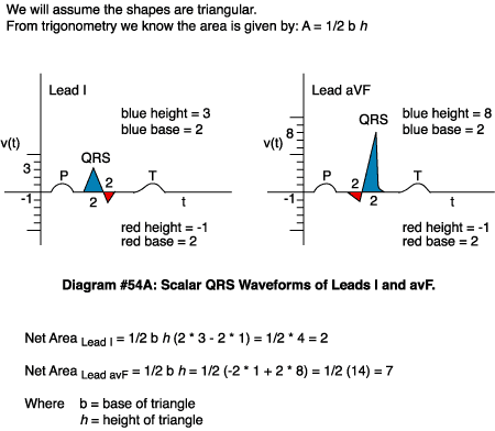
For those inclined to review the details, here is an example of axis calculation:
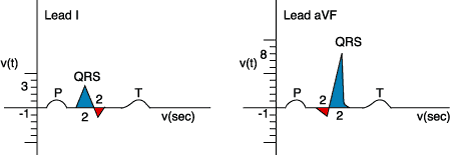
Net Area Lead I = 1/2 b h (2 * 3 – 2 * 1) = 1/2 * 4 = 2
Net Area Lead avF = 1/2 b h = 1/2 (-2 * 1 + 2 * 8) = 1/2 (14) = 7
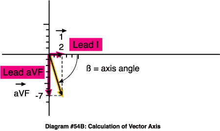
The vector diagram then becomes:
B = tan -1 3.5 = 74 degrees = Normal Axis
Note: For other Example Axis Calculations see the 12-lead ECG Workbook page 28 and Text Appendix A-2 in back of the 12-lead ECG Textbook.
Net Area Lead I = 1/2 b h (2 * 3 – 2 * 1) = 1/2 * 4 = 2 Net Area Lead avF = 1/2 b h = 1/2 (-2 * 1 + 2 * 8) = 1/2 (14) = 7
CASE STUDY
You are a member of a jeopardy team from your alma mater competing with a long-time rival university. The question (final jeopardy) is: “What is the approximate QRS axis of the tracing below?”
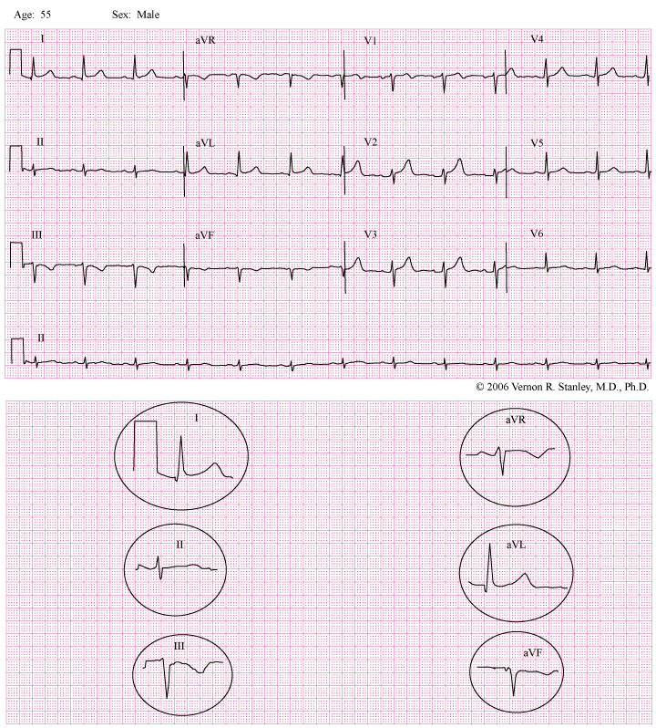
ANSWER
Approximate axis = – 30 degrees
TOPIC OF DISCUSSION
This lesson is specifically directed to the topic of the electrical axis, more particularly the QRS axis of the frontal plane. This axis is determined by the limb leads I, II, III, avR, avL, avF. For emphasis I have sampled and magnified each of these six leads and will refer to select ones in my following discussion.
GENERAL CONCEPTS
The electrical axis is best calculated by borrowing from the mathematics concepts of vector analysis. The electrical axis is described as the vector direction of the resultant depolarization wave of the free right, left ventricle and the septum. This vector can be found by the resultant of two vectors directed at 90 degrees to each other.
We will agree to use the following two vectors:
Lead avF (pointing straight downward)
and
Lead I (pointing horizontal and to the patient’s left)
The resultant of these two vectors is found as the diagonal of the rectangle formed by the two vectors:
Equation 1: Axis Vector = avF Vector + Lead I Vector
Equation 1………………….Axis Vector = avF Vector + Lead I Vector
The magnitude of the axis vector is found using the Pythagorean Theorem as follows:
Equation 2………………….. | Axis Vector | squared =………| avF Vector | squared + | I Vector | squared
Taking the square root of each side, Equation 2 becomes:
Equation 3……… | Axis Vector | = Square Root of [ (avF Vector) squared + (I Vector) squared ]
The angle direction of the electrical axis is calculated using the principles of trigonometry as follows:
Equation 4………. axis angle = arc tangent ( | avF vector | / | I vector | )
where…… tan -1 = arc tangent.
EXAMPLE AXIS CALCULATION
For the sake of example let us consider the special case of
| avF vector | = 1
| I vector | = square root of 3
Equation 4 becomes:
Angle of Axis = arc tangent ( 1 / square root of 3 ) = arc tangent ( square root of 3 / 3 )
Angle of axis = 30 degrees
It can be shown that, if the electrical axis is – 30 degrees, Lead II will be equiphasic, i.e. the positive area of the QRS complex will equal the negative area.
SPECIAL CASE OF AXIS = – 30 degrees
The key to the calculation of the axis lies in Lead I and Lead avF. It can be shown that if the following triad holds true:
- Lead I = dominantly positive
- Lead avF = dominantly negative
- Lead II = Equiphasic (positive area = negative area)
We can conclude
Equation 4 axis = – 30 degrees
SPECIAL CASE OF AXIS = – 45 degrees
It can be shown that if the following triad holds true:
- Lead I = dominantly positive
- Lead avF = dominantly negative
- | Net area Lead I | = | Net area Lead avF |
Equation 5 axis = – 45 degrees.
TRIAD OF LAFB
The Left Anterior Fascicular Block (LAFB) is characterized by the following triad:
1. Axis more negative than -45 degrees.
2. Small R-wave in Leads II, III, avF.
3. Small Q-wave in Leads I, avL.
From Equation 5 above we can clearly see that the Triad of the LAFB is equivalently stated as follows:
1. Lead I = positive
Lead avF = negative
| Lead I | = | Lead avF |
2. Small R-wave in Leads II, III, avF.
3. Small Q-wave in Leads I, avL.
See Dr. Stanley’s H*E*A*R*T Rule for clinical tool reference.
PEARL AND CONCLUSION
Normal Axis (between 0 degrees and 90 degrees)
Lead I = dominantly positive
Lead avF = dominantly positive
____
Axis – 30 degrees
Lead I = dominantly positive.
Lead avF = dominantly negative.
Lead II = equiphasic (positive = negative).
____
Axis – 45 degrees
Lead I = dominantly positive.
Lead avF = dominantly negative.
| Lead I | = | Lead avF |.
_____
LAFB
1. R-wave Lead II, III, avF.
2. Q-wave Lead I, avL.
3. Axis < or = – 45 degrees.
From this Case Study tracing, please note that I have magnified all six limb leads and will ask you to particularly notice the characteristics of Lead I, Lead avF and Lead II:
Lead I is dominantly positive.
Lead avF is dominantly negative.
Lead II is characterized by: Positive area = negative area (equiphasic)
We therefore conclude from Equation 4 that the axis = -30 degrees.
COROLLARY: If Lead II is predominantly negative, you can conclude that the axis is more negative than – 30 degrees.
ANSWER
Approximate axis = – 30 degrees
Question: True or False? The computer interpretation of the 12-lead ECG is very reliable and should be used regularly in clinical practice.
ANSWER: False. Typically, the use of the computer interpretation is never advised as it notoriously provides vague, nonspecific and unreliable interpretations. However, there are a few instances where the computer interpretation may be utilized. Axis is one of a few such cases.
For a detailed online-only course, we recommend the 50 Case Studies (13 Hrs Cat I CME/CE).
-
Sale Product on sale
 50 ECG Case Study Packet | Textbook, Workbook, HEART Ruler + 13 Hours Cat I CME
$273.49Original price was: $273.49.$239.00Current price is: $239.00. -
Sale Product on sale
 BOGO: 12-lead ECG Course + 50 ECG Case Study Course (43 Hours Cat I CME/CE) | 50% Off
$644.00Original price was: $644.00.$569.00Current price is: $569.00. -
Sale Product on sale
 BOGO: 12-lead ECG Course + Animated ECG Rhythm Course (39 Hours Cat I CME/CE)
$624.00Original price was: $624.00.$559.00Current price is: $559.00. -
Sale Product on sale
 Unisex HEART Mnemonic Long Sleeve Black T-shirt
$39.50Original price was: $39.50.$34.00Current price is: $34.00. -
Sale Product on sale
 12-lead Textbook, Workbook & HEART Ruler Packet
$124.00Original price was: $124.00.$110.00Current price is: $110.00. -
Sale Product on sale
 50 ECG Case Study & STEMI Review Combo Pack (19 Hrs CME)
$235.00Original price was: $235.00.$199.00Current price is: $199.00. -
Sale Product on sale
 Starter Online ECG 3-course Suite (22 Hrs CME | ACLS Prep + STEMI + 50 Cases)
$300.00Original price was: $300.00.$265.00Current price is: $265.00. -
Sale Product on sale
 Women’s HEART Acronym Fitted T-Shirt
$28.99Original price was: $28.99.$24.00Current price is: $24.00. -
Sale Product on sale
 Cheat Sheet Combo Pack: HEART Mnemonic + ECG Rhythm Ruler
$29.00Original price was: $29.00.$18.00Current price is: $18.00.


